News


How to Install a Rainwater Harvesting System: Step-by-Step
10 Sept 2026How to Install a Rainwater Harvesting System: Step-by-Step Guide
Installing an underground rainwater harvesting system correctly is the single biggest factor in whether it performs well for decades. A well-built system captures thousands of litres from your roof every year, cutting mains-water bills for garden irrigation and vehicle washing while reducing stormwater runoff. The installation itself takes only a few days, but mistakes made then are expensive to fix afterwards. In fact, installation errors cause more rainwater harvesting system failures than any other factor — more than undersized tanks, more than pump failures, more than poor filtration. The three most common mistakes are asymmetric backfilling (causes module tilt and uneven loading), skipping the base slab (causes settlement), and using the wrong geotextile specification (causes infiltration blockage or leakage).
This guide walks through the nine-step installation process that professional contractors follow for underground PP modular rainwater systems. Each step references Yingyuan's installation specifications derived from CJ/T 542-2020 and CJJ/T 311-2020 standards.
Nine-Step Installation Process
Step 1: Site Survey and Marking
Before breaking ground, confirm three things:
• Groundwater level: The module base must sit at least 1 m above the seasonal high groundwater table. If groundwater is closer than 1 m to the surface, the installation depth must be reduced or an alternative location selected.
• Underground utilities: Mark all existing services (gas, water, electricity, telecom) using utility plans and a cable detector. Maintain 500 mm clearance from any service.
• Soil investigation: A basic trial pit confirms soil type, bearing capacity, and the presence of rock or fill material that would affect excavation method.
Step 2: Excavation
Excavate to the required depth using this formula:
For a 3-layer Hurricane HD array (600 mm total module height), the excavation depth is approximately 1,150 mm. Maintain 200 mm clearance on each side of the module array for working space and membrane overlap.
Worked example: for a 3-layer array with 600 mm total module height: pit depth = 600 (modules) + 200 (base slab) + 150 (top cover) + ~200 (working space) = ≈ 1,150 mm. Use the same arithmetic for any configuration — stack height plus 550–600 mm for slab, cover and working allowance.
Excavation sides should be vertical or near-vertical in stable soils. In loose or sandy soils, batter the sides at 45° or install temporary shoring for pits deeper than 1.2 m.
Step 3: Concrete Base Slab
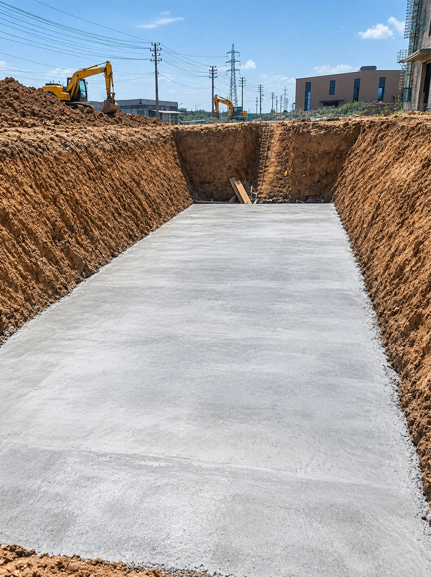
Pour a 100–150 mm C20 concrete (a standard general-purpose structural mix rated at 20 N/mm² compressive strength, commonly used for house foundations and base slabs) base slab, levelled to ±10 mm tolerance across the full array footprint. The slab provides a stable, flat foundation that prevents differential settlement under load.Allow 24–48 hours curing before placing modules.
Step 4: Geotextile Layer 1 (Bottom + Sides)
Lay the first layer of non-woven geotextile (200 g/m² minimum) across the base slab and up the sides of the excavation, with 300 mm excess beyond the pit edge on all sides. This layer serves as a separation barrier between the module array and the surrounding soil.
For sealed storage systems (rainwater reuse without infiltration), use 0.5 mm PE geomembrane (a flexible, waterproof plastic liner) instead of geotextile. Overlap membrane seams by 300 mm and heat-weld or tape with compatible sealing tape.
Step 5: PE Membrane Layer (Waterproof Barrier)
For sealed storage configurations, lay a second PE membrane layer over the geotextile. This dual-layer approach provides redundancy: the geotextile protects the membrane from puncture by sharp stones in the base slab, while the membrane provides the watertight seal.
For infiltration systems, skip this step — water must pass through the geotextile into the surrounding soil.
Sealed storage system | Infiltration system | |
What happens to the water | Stored for later reuse (irrigation, flushing, washing) | Soaks away into the surrounding soil |
Liner required | Geotextile + 0.5 mm PE geomembrane (Steps 4, 5 and 8) | Geotextile only (Step 4) |
Step 5 (PE membrane layer) | Required | Skip |
Step 8 (sealing the wrap) | Heat-weld or tape all seams into a watertight envelope | Fold geotextile over and overlap seams |
Typical use | Clay soils, high groundwater, or water reuse | Free-draining sandy or gravelly soils |
Step 6: Module Assembly
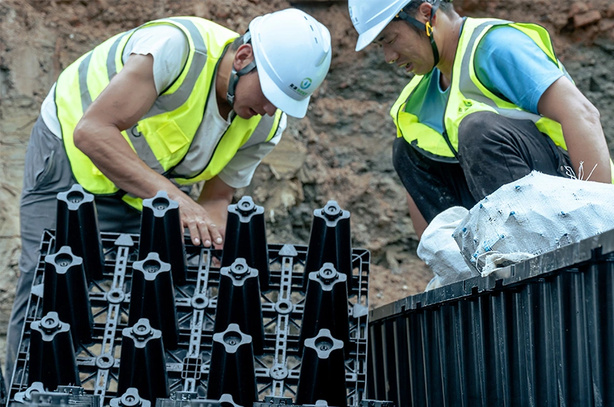
PP stands for polypropylene — a tough, corrosion-resistant plastic. Yingyuan PP modules are large plastic crates that connect via snap-fit interlocking columns (push-fit connectors that click together without bolts, welding or heavy machinery). No bolts, no welding, no heavy machinery.
(Figure to add: close-up of the snap-fit interlocking connection between two modules.)
Assembly method:
1. Place the first module on the base slab in the designated corner position
2. Snap adjacent modules into position, aligning column sockets with rib connectors
3. Stack subsequent layers with a half-module offset (staggered joints) for structural continuity
4. Continue until the array reaches the designed height
Two to three workers can assemble 10 m³ per day. The modules weigh 5–12 kg each depending on the model, well within manual handling limits.
Key checkpoints:
• Each connection must produce an audible "click" confirming the lock is engaged
• Array must be level (±5 mm across the full footprint) after each layer
• Inspection well pipe must be installed simultaneously with module placement (Step 7)
Step 7: Inspection Well Pipe Installation
Install a 200–300 mm diameter HDPE (high-density polyethylene — a hard, chemical-resistant plastic commonly used for buried pipework) inspection well pipe vertically through the module array, with the top extending 200 mm above the final ground level. This pipe provides access for future inspection, sediment removal, and pump maintenance without excavation.
Secure the pipe to the module array using the manufacturer's clip system. Seal the pipe-to-module junction with a rubber gasket to prevent soil ingress.
Step 8: Top Geotextile + Membrane Wrap and Seal
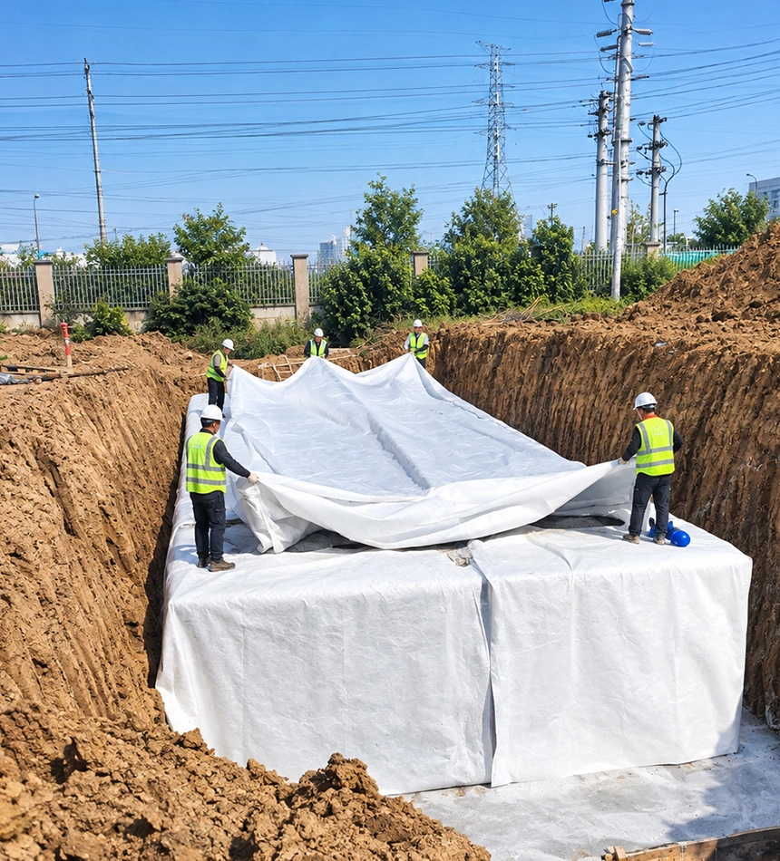
Fold the excess geotextile and membrane from Step 4 over the top of the module array, overlapping seams by 300 mm minimum. For sealed systems, heat-weld or tape all membrane overlaps to create a continuous watertight envelope.
The completed wrap should fully enclose the module array on all six sides, with no gaps at corners or pipe penetrations.
Step 9: Symmetric Backfilling
Backfill around and over the module array in 200 mm layers, compacting each layer to 95% Modified Proctor density — a standard laboratory measure of how tightly soil can be compacted; 95% is the level normally required beneath roads and structures.
The critical rule is symmetric backfilling: add material to all four sides of the array at the same time, keeping each side at roughly the same height, and compact each 200 mm layer before adding the next. Never fill one side completely before the others — asymmetric backfill creates lateral pressure differences that can tilt or shift the module array. (Figure to add: plan view comparing correct even four-side backfilling with incorrect one-side-first backfilling.)
Backfill material: Clean, well-graded granular material (sand, gravel, or crushed stone with maximum particle size 40 mm). Do not use clay, organic material, or construction debris.
Top cover: The final 150 mm above the module array should be topsoil for landscaping, or asphalt/concrete base for paved surfaces.
Tools and Materials Checklist
Tools Required
• Plate compactor (walk-behind, 80–100 kg)
• Spirit level (1,200 mm minimum)
• Measuring tape (30 m)
• Utility knife (for geotextile/membrane cutting)
• Heat gun or membrane welding tool (sealed systems only)
• Cable detector / utility scanner
• Hand tamper (for confined areas)
Materials Required (per 10 m³ system)
Material | Quantity | Specification |
PP modules | ~52 units (Standard 1000) | 1000×500×200 mm |
Non-woven geotextile | ~35 m² | 200 g/m² minimum |
PE geomembrane (if sealed) | ~35 m² | 0.5 mm thickness |
C20 concrete | ~0.5 m³ | For base slab |
HDPE inlet/outlet pipes | As designed | 110–160 mm diameter |
Inspection well pipe | 1 length | 200–300 mm diameter |
Backfill material | ~8 m³ | Clean granular, 40 mm max |
Note: 'Standard 1000' is the module size — each unit measures 1,000 × 500 × 200 mm (L × W × H). Confirm the module count against your design's required storage volume before ordering.
Frequently Asked Questions
How long does it take to install a modular rainwater harvesting system?
A 10 m³ system installs in 2–3 working days with a crew of 3–4 people. A 50 m³ commercial system takes 5–7 working days. A 500 m³ municipal installation may require 4–6 weeks. Module assembly is the fastest phase — excavation and backfill typically consume more total time.
Do I need a permit to install an underground rainwater tank?
Requirements vary by jurisdiction. In the UK, most residential installations fall under Permitted Development rights and do not require planning permission, but Building Regulations Part H3 compliance is mandatory. In the US, check with your local authority — some municipalities require a plumbing permit for systems connected to indoor plumbing. Commercial installations typically require both planning and building control approval.
Can I install a rainwater harvesting system in clay soil?
Yes, but clay soil changes the system configuration. Low permeability clay (<15 mm/hr infiltration rate) means you should use a sealed storage design (geomembrane-wrapped) rather than an infiltration design. The stored water is reused rather than dispersed into the surrounding soil.
For UK projects, a BRE Digest 365 percolation test — a standard field method published by the UK's Building Research Establishment for measuring how quickly water drains from a trial hole — determines whether infiltration is viable.
What is the minimum burial depth for PP modules?
The minimum cover above the top of the module array is 150 mm for pedestrian areas and 300 mm for vehicle-traffic areas. The maximum burial depth depends on the module model: Standard 1000 supports up to 3.5 m cover; Hurricane HD supports deeper installations.
This article is part of our complete rainwater harvesting system guide. For component specifications, see the system components buyer's guide. For post-installation maintenance, see the annual maintenance checklist. For installation-friendly modules, explore the Large 1200.
Related Reading
If you have already chosen a system, the installation overview in our rainwater harvesting guide, snap-fit PP modular tanks, rainwater harvesting maintenance checklist, rainwater harvesting tank size guide and Get a Quote.