News


SuDS Design Principles: Infiltration, Attenuation & Quality
23 Oct 2026The Four Pillars and the SuDS Management Train
The CIRIA C753 SuDS Manual — the definitive UK reference for sustainable drainage design — structures every SuDS scheme around four pillars: water quantity, water quality, amenity, and biodiversity. A scheme that addresses only flood storage without considering treatment, public access, or habitat creation will struggle to gain planning approval under current SAB requirements. Designers who treat all four pillars as equal priorities from the outset produce schemes that pass scrutiny faster and perform better over their operational life.
Water quantity management means controlling both the volume and rate of runoff leaving a site. The UK SuDS National Standards require that developments manage the 1% AEP (annual exceedance probability) extreme rainfall event — effectively the 1 in 100 year storm — with an allowance for climate change. Additionally, the first 5 mm of daily rainfall must be intercepted and managed through the drainage hierarchy: reuse first, then infiltration, then discharge to a watercourse, and only as a last resort to the public sewer.
Water quality is addressed by treating runoff through a sequence of components, each removing a proportion of the pollutant load before water reaches the next stage or the receiving environment. Amenity requires that SuDS features serve a usable purpose beyond drainage — a detention basin that doubles as a playing field, or a swale that forms part of a landscaped entrance. Biodiversity demands that SuDS create or enhance habitat, a requirement now tightly linked to Biodiversity Net Gain (BNG) obligations under the Environmental Improvement Plan 2025.
The Management Train
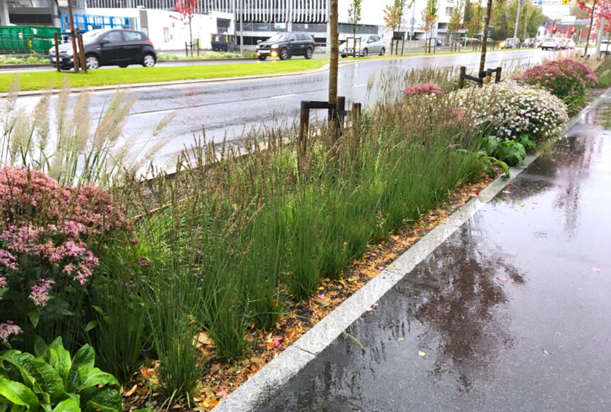
The management train is the organising principle that connects these four pillars in practice. It sequences SuDS components from source (roof and paving level) through site (plot and street level) to regional (catchment level). At each stage, the component intercepts, stores, treats, or conveys water before passing any excess to the next tier. A well-designed train ensures that no single element carries the entire drainage burden, and that water quality improves progressively as runoff moves through the system.
SuDS types used across the management train include permeable paving, rain gardens, bioswales, detention basins, constructed wetlands, soakaway crates, and attenuation tanks. For urban sites with limited surface area, geocellular crates are the most common underground component, providing high-volume storage within a compact footprint.
Two fundamental design strategies sit at the heart of the quantity pillar: infiltration and attenuation. Choosing between them — or combining them — depends on site geology, groundwater conditions, contamination risk, and the discharge hierarchy mandated by the SAB.
Infiltration Design: BRE 365 and Soakaway Sizing
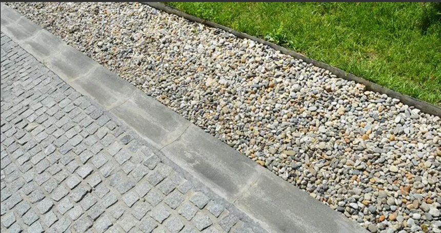
Infiltration SuDS returns rainwater to the ground, recharging groundwater and eliminating surface discharge. Where site conditions permit, infiltration is the preferred approach under the drainage hierarchy, and it is typically the simplest route to SAB approval.
BRE 365 Infiltration Testing
Before any infiltration-based SuDS can be designed, the ground's infiltration capacity must be established through on-site testing. The standard method in the UK is the BRE 365 soakaway test, which measures the rate at which water drains from a trial pit into the surrounding soil.
The test involves excavating a pit to the proposed invert level of the SuDS feature, filling it with clean water to a recorded depth, and measuring the time taken for the water level to drop. Multiple repetitions — at least three — are required to establish a reliable design infiltration rate. The test should be conducted during the wettest part of the year, when the water table is at its highest and infiltration rates are at their lowest, to ensure that the design works under worst-case conditions.
Typical infiltration rates vary enormously by soil type. Clean sand and gravel may achieve rates above 1,000 mm/hr, while silty clays can fall below 10 mm/hr, and heavy boulder clays may be effectively impermeable. Where rates fall below approximately 15 mm/hr, infiltration-only designs become impractical and an attenuation approach — or a hybrid system — should be considered.
Sizing a Soakaway
Once the infiltration rate is known, the soakaway is sized to store the design storm volume and release it within a target drain-down period. The standard design storm for extreme event sizing in the UK is the 1% AEP event. Most local planning authorities require the soakaway to drain from full to half-full within 24 hours, ensuring that capacity is available for a second consecutive storm event.
The calculation follows a straightforward volume balance:
1. Calculate the design runoff volume entering the soakaway, based on catchment area, runoff coefficient, and design storm depth.
2. Determine the required storage volume — this is the difference between inflow volume and the volume that infiltrates during the storm event.
3. Size the soakaway structure to provide that storage, accounting for the void ratio of the fill material.
The void ratio of the storage medium is critical here. Traditional rubble or granular fill achieves only around 30% void space, meaning that a large excavation is needed for relatively modest storage. Modular geocellular crates, by contrast, achieve a void ratio of 92%, substantially reducing excavation volume for the same effective storage.
For underground geocellular systems, the crates must be specified for the loads they will carry. Vertical pressure ratings range from 35 tonnes to over 70 tonnes depending on the model, allowing installation beneath car parks, access roads, and landscaped areas. Maximum cover depths of up to 3.5 metres provide flexibility for sites with deep services or complex grading.
When Infiltration Is Not Feasible
Infiltration is not suitable on every site. High water tables, contaminated ground, clay soils with low permeability, and proximity to building foundations can all rule it out. In these cases, the design must shift to an attenuation strategy — storing runoff and releasing it at a controlled rate to a watercourse or, with permission, to the public sewer.
Attenuation Design: Storm Events, Storage, and Freeboard
Attenuation SuDS stores excess runoff and releases it at a rate that does not exceed the pre-development (greenfield) discharge rate. This is the approach required where infiltration is not feasible, or as a secondary measure alongside infiltration to handle extreme events.
Step 1: Determine the Design Storm
The UK SuDS National Standards specify the 1% AEP event as the design standard for extreme rainfall. In practice, many LPAs also require that the system manages a 1 in 30 year storm for the water quality volume — the first flush that carries the highest pollutant concentration. Climate change allowances are added to both, typically as a 20% to 40% uplift in rainfall depth depending on the project's design life and the relevant regional allowance published by the Environment Agency.
Step 2: Calculate the Allowable Discharge Rate
The permitted discharge rate from a developed site is normally restricted to the pre-development greenfield runoff rate. This is the flow that the site would have generated before construction, calculated using standard hydrological methods (such as the Flood Estimation Handbook or the UKSuDS.com greenfield runoff tool). The principle is straightforward: development should not increase the flood risk downstream.
Step 3: Compute Storage Volume
The required storage volume is the difference between the total runoff generated during the design storm and the volume that can be discharged at the allowable rate over the same period. This is calculated using hydrograph analysis, where the inflow hydrograph (runoff from the developed site) is superimposed on the outflow hydrograph (controlled discharge at the greenfield rate).
Worked example: A 0.5-hectare commercial development on clay soil requires an attenuation system. The 1% AEP, 6-hour design storm produces approximately 150 m³ of runoff from the site. The greenfield discharge rate is 5 litres per second. Over the 6-hour storm, the site can discharge 5 L/s × 21,600 s = 108 m³. Required storage: 150 − 108 = 42 m³.
Using geocellular crates with a void ratio of 92%, the physical crate volume required is approximately 42 ÷ 0.92 ≈ 46 m³. These modules, assembled from precision-moulded PPB components with groove and rib column connections, can be installed to cover depths of up to 3.5 m and configured to fit irregular site boundaries.
Step 4: Freeboard and Safety Margins
Freeboard is the additional storage capacity provided above the calculated design volume to account for uncertainty in rainfall estimates, potential blockages in flow control devices, and the possibility of storms exceeding the design event. UK and Irish guidance recommends a minimum freeboard of 150 mm to 300 mm for SuDS storage features.
For underground attenuation tanks, freeboard is achieved by oversizing the tank — typically adding 10% to 20% to the calculated storage volume. This buffer is essential: an attenuation tank that operates at full capacity during the design storm has no reserve for the inevitable occasions when rainfall exceeds predictions or when silt accumulation reduces effective storage.
The structural design must also account for worst-case loading. Ultimate limit state (ULS) analysis verifies that the crate system can withstand the combined effects of saturated ground, full surcharge loading, and hydrostatic uplift without failure. Products tested to CJ/T 542-2020 heavy-duty standards provide documented assurance of structural capacity across the specified load range.
Water Quality: Treatment Stages and Pollution Removal
The water quality pillar of SuDS design requires that runoff is treated before reaching a watercourse or groundwater. Treatment is achieved through a combination of physical, chemical, and biological processes — filtration, sedimentation, adsorption, and biological uptake — distributed across the management train.
Removal Rates by SuDS Component
Different SuDS components target different pollutants, and performance varies with design detail, maintenance, and local conditions. The following figures are drawn from monitored UK and international studies:
Permeable paving: removes 60% to 80% of runoff volume, 70% to 90% of suspended solids (SS), and 50% to 70% of total phosphorus (TP).
Green roofs: intercept 50% to 70% of rainfall, with Mediterranean climate studies recording 40% to 65% depending on substrate and planting.
Combined LID measures across a catchment: reduce annual runoff by 30% to 50% and peak flow by 40% to 60%. The cumulative effect also reduces total pollutant loads reaching watercourses, since volume reduction and treatment occur at every stage.
Geocellular Crates and Water Quality
Geocellular attenuation crates function primarily as storage, not treatment. They are designed to hold water temporarily and release it at a controlled rate. To protect water quality and prevent the crate void from filling with sediment, upstream pre-treatment is essential. This typically takes the form of silt traps, vortex separators, or filter cartridges installed in manholes or catchpits before the inlet to the crate system.
Within the crate itself, some additional settlement occurs as water velocity drops to near-zero in the stored volume. The precision-moulded groove and rib column design of modern PP modules promotes even flow distribution, reducing short-circuiting and maximising the effective residence time for sedimentation.
For sites where harvested stormwater is destined for agricultural reuse — such as irrigation or livestock watering — water quality management is particularly important. The treatment train must ensure that the stored water meets the required standards for its intended end use and does not carry pathogens, heavy metals, or hydrocarbons that could contaminate crops or soil.
Designing for Ultimate Limit State
Every water quality and storage component must be verified against ultimate limit state (ULS) failure modes. For underground systems, this means confirming that the crate structure, surrounding geotextile or membrane wrap, and all connections can withstand the combined loading of saturated backfill, traffic surcharge, and hydrostatic pressure without structural compromise. Testing to heavy-duty standards during the product certification period provides the engineering evidence that structural designers and specifying engineers require.
Frequently Asked Questions
What is the SuDS management train?
The management train is the principle of treating and managing runoff through a sequence of SuDS components arranged from source (roof, paving) through site (plot, street) to regional (catchment) scale. Each stage intercepts, stores, filters, or conveys water, so that the drainage burden is shared across multiple features rather than concentrated in a single end-of-pipe solution.
How do I choose between infiltration and attenuation?
The decision rests on site conditions. If the ground has adequate permeability (confirmed by BRE 365 testing), no contamination risk, and a low water table, infiltration is the preferred route under the UK drainage hierarchy. Where any of these conditions cannot be met, attenuation — storing runoff and releasing it at the pre-development greenfield rate — is the appropriate alternative. Many schemes combine both: infiltration for frequent, small events and attenuation for extreme storms.
What freeboard allowance should I include in SuDS storage design?
UK and Irish guidance recommends a minimum freeboard of 150 mm to 300 mm for SuDS storage features. For underground geocellular attenuation tanks, this translates to approximately 10% to 20% additional storage above the calculated design volume. The freeboard accounts for blockages, silt accumulation, and rainfall exceeding the 1% AEP design event.
What structural loads can underground SuDS crates withstand?
Geocellular crate systems rated for heavy-duty applications can withstand vertical pressures ranging from 35 tonnes to over 70 tonnes per unit, depending on the model specification. Products tested to CJ/T 542-2020 heavy-duty standards are verified for installation beneath car parks, access roads, and landscaped areas with cover depths of up to 3.5 metres. Structural designers should verify the specific model against site loading conditions using ULS analysis.
For a full explanation of the SuDS framework, start with our guide to What Is SuDS. To understand how to calculate storage volumes in detail, see How to Calculate SuDS Attenuation Volume. For product selection, explore our geocellular attenuation tank range. For rainwater storage volume calculations from a harvesting perspective, our rainwater storage volume guide provides complementary methodology.
This article is part of our complete SuDS Solutions: The Complete Guide to Sustainable Drainage Systems, which brings the design principles, attenuation sizing and product selection covered here into one framework.